

 At first you will find at this place only the wiring diagrams of the
universal Delta decoders (for convenience I will name them V1, V2, V4 and V5) as well as other loco-
specific Delta decoders with the 701.17(b) I got to know about. You can download the diagrams
as a zip-file and study them leisurely. For that purpose you can click on the reduced figures
provided that your browser saves zip-files to disk or asks you what to do with such a file.
At first you will find at this place only the wiring diagrams of the
universal Delta decoders (for convenience I will name them V1, V2, V4 and V5) as well as other loco-
specific Delta decoders with the 701.17(b) I got to know about. You can download the diagrams
as a zip-file and study them leisurely. For that purpose you can click on the reduced figures
provided that your browser saves zip-files to disk or asks you what to do with such a file.
With some details though we are stuck despite strenuous brooding. If someone knows the types or values of the respective components please drop me a line. The function of the circuit around pin 5 of the 701.17(b) on the V1 was cleared up by Bo Braendstrup to whom I am indebted: in analogous AC mode (DIP switches set to "0000") the high voltage pulse for redirection is detected by the zener diode and the resistors. Normally on pin 5 is a voltage of 0V; it increases to ca. 5V during the reversing pulse resulting in (a) in a redirection signal and (b) a deactivation of the outlets pin 9 and 10. The respective circuits inthe other decoder-versions work likewise as Martin Rothschink has told me; his co-operation is gratefully acknowledged. He has further pointed out that regarding this detail the present circuits are less reliable with the versions V1 and V4 than with V2 and V3 because you run the risk that the 701.17(b) is confronted with a voltage higher than its supply voltage - a condition not necessarily conducive to its durability. Dipl.Ing. Manfred Röhrig has learned from Dr. Konrad Froitzheim that the quartz between pin 1 and 2 of the 701.17(b) is a plain clock quartz with 32 kHz; many thanks to them as well. Roelof Salters suggests to decrease the base-resistors of the function-transistors significantly (4k7 to 5V, 10k to power-supply), because the power-dissipation of these transistors may increase the allowed limit at higher currents. K. Segebrecht has given me notice of an error in te circuit of the decoder # 66415 (deltneu3.bmp) - thanks to him.
Meanwhile I can also offer the circuit of the Delta-TELEX-decoder No.66031. Here is nothing to explain; the special-chip 701.21 is managing all alone. Unfortunately there is no way to activate the auxiliary function: The chip is manufacted with and without activated auxiliary function and normaly the "castrated" version is used on the 66031.
Siegfried Grob has analyzed another version of the 66031; circuit and layout of this decoder is really different
and looks like very strange.
Also without further explanations is the circuit of the 66032-decoder, which was analyzed by Dipl.-Ing C. Joachim Schröder. Here also only one chip - the 701.43A - is managing all the actions; the function of the motor-driver (IRF7103) and the drivers for light and TELEX (BST52) is very easy to understand.
 Elsewhere is described how the old Delta decoder can be extended by the auxiliary function; this version of the decoder
can be recognised by the trait that the loco address is not set by DIP switches but by solder
bridges. Here you find the desription how to do it with the successor, the Delta decoders 6603 (with the chip 701.17 onboard). But this is not possible with the new Delta-decoder 66031 with the 701.21 onboard.
Elsewhere is described how the old Delta decoder can be extended by the auxiliary function; this version of the decoder
can be recognised by the trait that the loco address is not set by DIP switches but by solder
bridges. Here you find the desription how to do it with the successor, the Delta decoders 6603 (with the chip 701.17 onboard). But this is not possible with the new Delta-decoder 66031 with the 701.21 onboard.
In the meantime I have discovered how to activate the four extra functions available with the new protocol. Further explanations you find below.(mr)
I will only describe the conversion for decoders with the 701.17(b) and 701.13 chips since these are the only ones that I own or have access to. I cannot be certain whether or not older decoders can be converted as well. In addition, the following refers only to the standard Delta decoders; specialty versions, e.g. smaller types may use different circuit boards.
The 701.13/701.17(b) provides a direction dependent function that usually serves to control the locomotive headlights. The digital (6080) and 6090 decoders contain circuitry utilizing these outputs. Almost all Delta decoders contain much of the necessary components on the circuit board. However, Märklin chooses to connect the output driver transistors to the motor output instead of the chip's function outputs. This apparently is designed to provide an incentive for customers to discard the Delta decoders they already paid for and replace them with much more expensive digital and 6090 decoders. The flip side of this customer-unfriendly policy (?marketing strategy?) is that Delta decoders can be converted fairly easily, even though Märklin has revised the more recent layout versions to make the process more difficult. The modifications described in the following paragraphs are explained also in MIBA Spezial 37.
 Therefore, the necessary modifications merely require disconnecting the
driver transistors from the motor output and reconnecting them to the
function outputs. Since these outputs are of the "open collector" type, two
additional pull-up resistors must be wired between the outputs and the
positive supply voltage. The corresponding changes are indicated in the
circuit diagrams. If you want to connect the Light/TELEX-add-on to the aux.-func.-output you must change the value of this resistors to 4k7.
Therefore, the necessary modifications merely require disconnecting the
driver transistors from the motor output and reconnecting them to the
function outputs. Since these outputs are of the "open collector" type, two
additional pull-up resistors must be wired between the outputs and the
positive supply voltage. The corresponding changes are indicated in the
circuit diagrams. If you want to connect the Light/TELEX-add-on to the aux.-func.-output you must change the value of this resistors to 4k7.
The additional light circuit modification (connecting lights to the supply
voltage instead of chassis ground = brown wire) is not necessary for the
basic additional function. However, this suggested addition eliminates the
annoying flickering of the lights and provides constant intensity. For this
modification it is necessary that both terminals of the light bulb
socket(s) are insulated from ground which is typically the case for newer
locomotives with plug-in type light bulbs. In older models each socket must
be modified to insulate the terminal originally connected to ground.
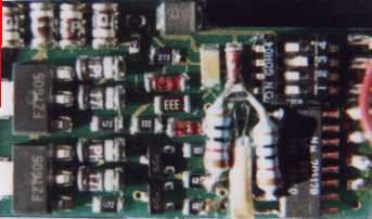
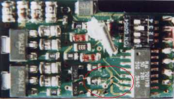
The adjacent picture illustrates the appearance after this modification.
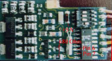 The adjacent illustration identifies the important locations for the
planned "surgery", in particular the function output pins 6 and 7, the 680
Ohm resistors which may have to be removed as well as the cathode end of
the Z diode which can be used to connect the pull-up resistors to the +5Vsupply voltage. The newer decoders have slightly different layouts.
The adjacent illustration identifies the important locations for the
planned "surgery", in particular the function output pins 6 and 7, the 680
Ohm resistors which may have to be removed as well as the cathode end of
the Z diode which can be used to connect the pull-up resistors to the +5Vsupply voltage. The newer decoders have slightly different layouts.
Although it should be obvious, I want to emphasize that this should only be attempted by someone experienced in soldering, and only after the 100W solder gun has been safely stored out of reach. I recommend using an 8W iron with a fine tip along with a steady hand and a good eye, preferably assisted by a loupe or magnifying glass. Keep in mind that a damaged 701.13/701.17(b) implies a dead decoder ready for the trash bin (or at best for parts salvage) since Märklin's customer-unfriendly policy ensures that you will get nothing but factory fresh new decoders - you will not have the questionable pleasure of unsoldering and replacing the 701.13/701.17(b). Replacement chips are not available for any amount of money or persuasion. Therefore you are soldering at your own risk - I am not responsible for damage to your decoder.
 First, lift the crystal (including the glue) to the left of the
701.13/701.17(b) off the board and carefully bend it up and towards the
top. Next, either remove the two 680 Ohm resistors or interrupt the circuit
board trace connecting them to the motor outputs (pins 9 and 10) of the
701.13/701.17(b), at the right lower corner. The illustrations depict the
latter.
First, lift the crystal (including the glue) to the left of the
701.13/701.17(b) off the board and carefully bend it up and towards the
top. Next, either remove the two 680 Ohm resistors or interrupt the circuit
board trace connecting them to the motor outputs (pins 9 and 10) of the
701.13/701.17(b), at the right lower corner. The illustrations depict the
latter.
The newer decoder versions using the ZDS1000 motor driver require
removal of these resistors along with interruption of the traces connecting
pins 6 and 7 to pin 8, best done with a sharp knife or scalpel. The layout
has apparently been changed in order to make our modifications more
difficult. Alternatively, unsolder pins 6 and 7 from the pads and carefully
bend them up a little; you may then wish to place a small piece of
electrical tape between the pins and the empty solder pads. Connect pins 6
and 7 to the free terminals of the 680 Ohm resistors or to the base
terminals of the transistors (usually labelled "C6"), or - if you removed
the resistors - to the empty pads connected to the transistors. The newer
decoders need to have pin 6 connected to the right most transistor. I use
fine enamel ("magnet") wire, but any insulated thin wire will do. This is
shown in the adjacent illustration.
Finally, connect two 10 kOhm (or 4k7) resistors
between pins 6 and 7 (or the corresponding 680 Ohm resistor pads),
respectively, and the cathode of the Z diode. Space is at a premium, and
very small (1/10 W) resistors work best. Standard 1/4 W resistors as shown
in the above illustration are a little more difficult to fit in. If you removed
the 680 Ohm resistors you can solder the 10 kOhm (or 4k7) resistors directly to the
free pads connected to the transistors' base terminals.
Carefully check all connections and make sure you didn't create any stray solder connections with other parts of the circuitry. Gently bend back the crystal towards its original position. Connect the lights as indicated, including the above described modification if so desired. These changes of the lightning (operating voltage instead of track ground/loco chassis) additionally sketched in the diagrams is not required for the functional extension of the Delta decoder. (kf)
As it is known the new data format does not only provide a definite reversing signal but also four additional functions called 'extra functions'. Märklin so far concealed that this feature is generally possible in HO also; on a direct request I was informed that in the foreseeable future no usage in HO and corresponding decoder is intended. But some half year later Märklin placed the first HO- locos with such decoder on the market - another example of the customer unfriendly disinformation policy of Märklin.
The new data format is fully recognised only by newer decoder with the 701.17 or 701.17b, i.e. older decoder (e.g. with the 701.13) cannot to be extended with the extra functions. The conversion requires some tricky soldering on the 701.17(b). Since this IC is quite sensitive it can easily fall by the wayside; Märklin refuses persistently to supply this chip as a spare part so consider the risk carefully. The conversion is done by de-soldering four pins of the chip and/or to rewire them. Depending on the decoder type more or less effort is needed. Furthermore another IC as well as one or two transistors along with resistors are to be connected.
 The principle of utilising the four extra
functions is based on the transmission of the respective data to a shift register and
providing this data on its outlets. The 'complete upgrade', i.e. to make all four
extra functions available, needs two CMOS shift registers of the type 4094. As two
extra functions normally do in HO one 4094 suffices.
The principle of utilising the four extra
functions is based on the transmission of the respective data to a shift register and
providing this data on its outlets. The 'complete upgrade', i.e. to make all four
extra functions available, needs two CMOS shift registers of the type 4094. As two
extra functions normally do in HO one 4094 suffices.
The 4094 is controlled by the pins 4, 6 and 7 of the 701.17(b) thus providing data signals as well as clock and strobe pulses. As a result, however, the auxiliary function (lights) cannot directly be
controlled by pin 6 and 7 of the 701.17(b). This is not as bad as it seems since this
function is then also handled by the shift register. If the 701.17(b) is already extended for the use of the auxiliary function (or with one of the rare 6090 with a 701.17) a
rewiring is unavoidable. The figure shows the pin assignment of the 701.17(b) to the
inlets of the 4094 and the register outlets as far as they are of interest here.
 For this upgrade pin 3, 4 and 5 of the 701.17(b) have to be detached from the pcb. On some
decoder types this might be necessary for pin 6 and 7 also or their connection to ground has to be
cut (this is not possible with pin 3 as the ground connection is located under the chip). Pin 3 is left
open; pin 5 is connected via a resistor 270k to track ground /loco-chassis (brown cable). Pins 4,
6 and 7 are linked with the 4094 according to the figure.
For this upgrade pin 3, 4 and 5 of the 701.17(b) have to be detached from the pcb. On some
decoder types this might be necessary for pin 6 and 7 also or their connection to ground has to be
cut (this is not possible with pin 3 as the ground connection is located under the chip). Pin 3 is left
open; pin 5 is connected via a resistor 270k to track ground /loco-chassis (brown cable). Pins 4,
6 and 7 are linked with the 4094 according to the figure.
In this circuit the "memory" of the decoder will not be influenced from lost of supply-voltage - in opposite to the 4094, which will loose his information/content . But the 701.17(b) will rebuild it in the following seconds (this time depends on the kind of controller you use) after re-establish the supply-voltage. Depending on the individual load you may decrease the base-resistors of the transistors which are connected to the 4094 to 10k - or better use darlintons-transistors or MOSFETs which switch at 5V (e.g. the SI9955/SI9965/SI9945).
One drawback of this upgrade should not
be concealed: henceforth an analogue operation is not possible as the 24 volts reversing pulse is
not recognised any more.
As an example the downsized figure depicts the necessary modifications on the tender specific
decoder. This works particularly well since some zero-ohm resistors are used as bridges that can
be easily detached. Furthermore the tender provides enough space for the supplementary circuit
consisting of conventional components.
You also can take the supply-voltage from the buffer-cap - at the anode of the zener or the cathode of the buffer-diode. So you make shure that the 4094 will not loose his information/content at lost of supply-voltage. But this will decrease the time of the "memory" of the decoder.
A third way is suggested by Peter Tröster: You have to switch the OE-input of the 4094 not to it´s supply-voltage (pin 15) but via a resistor of ca. 220k to the cathode of the zener or the anode of the buffer-diode - as you can see (without resistor) in the circuit-diagram. So only the output of the 4094 will be disabled at lost of voltage-supply but it´s informations/content will not be influenced.
The diodes marked with an asterisk are only a proposition
how to re-establish the compatibility to the analogue operation. I did not check this circuit, it is just a theoretical result of an analysis of the 24 volts detector circuit as well as the 6095 decoder; it
should work though. Since I cannot guarantee the survival of the 701.17(b) and the analogue
mode is of lesser interest to me, I am looking forward to a courageous 'mixed-mode railroader'
ready to risk a decoder.
You can download the diagram as a zip-file and study it leisurely. For that purpose click on the
downsized figure provided that your browser saves zip-files to disk or asks you what to do with
such a file. This can be configured in all common browser - e.g. in Netscape Navigator with
"option / general preferences / helpers".
Kenneth Pallund offers basing on this explanations a description of this modification, too.
 For those, who cannot etch own PCBs please contact Bo Braendstrup directly, he might even offer the complete circuit ready-made.
Last but not least I would like to gratefully acknowledge the kind help of Bo Braendstrup and also Dr. Konrad Froitzheim on this topic.(mr)
This translations were made by Dipl.Ing. Manfred Röhrig from Germany (mr) and Dipl.Ing. Klaus Fechner from USA (kf).
Many thanks to both for this grateful work. Some mistakes you probably find are my work as result of trying
to correct some misunderstandings and add some additions.

© 1997 by Dipl.Ing. Manfred Röhrig
| Nienstedter Straße 71 | 30890 Barsinghausen | roehrig@gem.uni-hannover.d400.de
© 1997 by Dipl.Ing. Klaus Fechner
| ... | Palo Alto, CA, USA | klaus@forsythe.stanford.edu