


With the booster there is only one answer for the hobbyist : "make", of course. Because the commercailly available boosters known to me have the big disadvantage that the output voltage is not stabilized - in spite of their fairly high price. The output voltage of the Marklin Control-Unit-Booster, and thereby the voltage of the digital signal on the tracks, fluctuates, depending on the load, between +/- 23 and +/- 15 V. It is obvious, that this causes very undesirable speed changes. Even the very good regulation of Marklin-6090-decoders cannot correct this. The lighting shows a disturbing flickering behavour because of this. An other reason for these voltage fluctuations is in the Marklin-transformers : they only supply fixed 16V AC, and are pretty weak, which means that with a serious load there is a considerable reduction in output voltage. It is of course very difficult to create a stabilised +/- 18V from that.
When building your own booster, one should be modest. 5A output current is enough in any case - may be even too much -, because with higher output rating, short-circuits may "weld" the weels to the rails, and cause other damage. I have had such experiences with my EDITS-booster, rated at 10A.

I have to add a remark to above circuit-diagram : I did develop this
circuit for the Marklin-system, but (originally) not for the
Control-Unit. My intention was to build a small booster for
LOK, that
would be driven directly from the PC-serial-port, without control-unit
or interface, quasi-digital, almost for free. Therefore I had to add a
small "interface" for the connection to the Marklin-CPU, which enlarges
the circuit a little bit.
In addition, I wanted to use the many 32VA Marklin-transformers, that I
have as left-overs from beginners-sets. One has to use some tricks, when
one wants to be able to use these transformers. These include "surgery"
on the transformer, to be able to use the 24V AC which is available
inside. One can, of course, also use a stable 18-22V transformer. The Marklin
tranformers have the advantage, that they have an integrated overload-
protection; and the high output impedance is compensated by the 24 V
available.
With the addition for the 6021, the booster has shown to be able to
operate with the Intellibox as well, without any change to that interface.
Although it was not designed for this, it also amplifies the SELECTRIX
digital signal in an acceptable way, at least as seen on the
oscilloscope. This is due to the connection/disconnection of the power
signal without the use of relais.
It is well-known, that the Control-Unit switches off the booster : the
output becomes "floating" and there is no more voltage on the tracks.
A well-designed booster must also perform this function; this is done
by the components between JP2 and IC3. They prevent voltage on the
tracks when the power-signal is absent. This is achieved at "electronic"
speed,- very fast- and therefore also very usefull for the SELECTRIX.
This system has the
peculiarity, that it switches not only between positive and negative, but
also, in between, to ground for about 10 microseconds. A relais is
obviously not capable of switching at this speed, this can only be done
electronically. I don't know if SELETRIX-decoders work well together with this circuit;
since I don't have any, I couldn't test this. The circuit may have to be
optimised for this application.
 The connection of the booster to the CU is done on the CU-side to the plug
dedicated to the booster; on the booster-side with the usual SUB-D-plug
that we know from the PC-serial-port. The pin-connections on the CU-plug are
(looking to the backside, starting from the left ):
The connection of the booster to the CU is done on the CU-side to the plug
dedicated to the booster; on the booster-side with the usual SUB-D-plug
that we know from the PC-serial-port. The pin-connections on the CU-plug are
(looking to the backside, starting from the left ):
The SUB-D-plug should be wired as follows :
pin 1 short-circuit
pin 2 data
pin 5 ground
pin 8 power
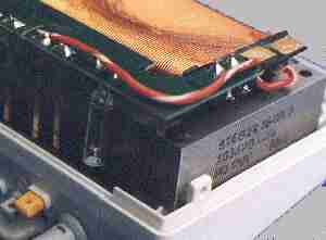
The cables that lead to the tracks are connected with two outlets for the standard Marklin plugs ( 2.6 mm miniature plugs) The cable for the mains is lead through a hole and safeguarded against mechanical pull with a wire-clamp. The picture shows the back of a prototype connected to a 32VA transformer that has been modified. Prototyps.
When looking at the sides, one can observe two small plasic plugs.
These can be removed by brute force, by drilling trough, but then one
has the problem that is no longer possible to close the box again in a
way that is child-proof. It is more elegant to drill small 1.5 mm holes in the plugs. If one is
lucky, the pins will attach to the drill, and can be pulled out. If not,
one can take a fitting screw and screw it into the hole. When it is
securely fastened, one can "pull the plug". Afterwards, it is advisable
to make an M2 or M2.5 thread in the plug, so that it becomes easier in
the future to remove these plugs, by simply screwing in a fitting bolt,
and pulling out the plug.
However, in newer trafos it has become increasingly difficult to remove
the plugs in this way. In that case, one has no other choice but to
completely remove these plugs by drilling. One should take care, only to remove
that part of the plug, that holds the top and bottom parts of the box
together. In this way, one can later use screws to close the box again.
 After removal of the four plugs one can remove the cover; one has to be
carefull with the wire between the two parts. The 24 V connection is now
visible on the left-hand side; it is the bottom one of the two copper
areas for the contact of the direction-change switch. A cable with appropriate
cross-section has to be soldered to this area, and to one of the two
brown ground-connections, which before has been isolated from the overal
ground. The picture to the right shows the open transformer box after above
changes have been made; the connection of the 24V is on the bottom side of the
PCB and not visible in the picture.When the box is closed, please make sure
that the cables are laid correctly, and not squeezed anywhere. After
repositioning of the plugs ( with M2 threads inside ) one should
distinguish the new 24V output plug from the others by giving it a new,
different color.
After removal of the four plugs one can remove the cover; one has to be
carefull with the wire between the two parts. The 24 V connection is now
visible on the left-hand side; it is the bottom one of the two copper
areas for the contact of the direction-change switch. A cable with appropriate
cross-section has to be soldered to this area, and to one of the two
brown ground-connections, which before has been isolated from the overal
ground. The picture to the right shows the open transformer box after above
changes have been made; the connection of the 24V is on the bottom side of the
PCB and not visible in the picture.When the box is closed, please make sure
that the cables are laid correctly, and not squeezed anywhere. After
repositioning of the plugs ( with M2 threads inside ) one should
distinguish the new 24V output plug from the others by giving it a new,
different color.
It is understandable that Marklin does not recommend this procedure; after this you can't any more go back to your dealer with any kind of damage, since he will claim that it is caused by your actions - it is not worth the effort, with the (low) price of these transformers. I have modified several of these transformers, and operated them over longer periods of time without any excessive heating - which is no surprise, since Marklin must have taken care of the possibility that children turn the knob "left" (=24V) for longer periods of time. (I did in my youth)
The two single-phase rectifiers allow a safe parallel use of two
transformers. It is well known that the parallel connection of the secondary windings
of two transformers, can cause 220 V to appear on one mains plug, when
it is - by -accident, pulled out of the wall-outlet. The shown circuit
avoids this problem; it is however recommended that both mains cables
from the two transformers be soldered together and connected to mains
via one, shared, plug. Attention should be paid to the polarity (phase ) of the transformers.
This can be done by connecting both brown outlets, and when one then briefly
connects the yellow ones, no short-circuit should be observed. Instead,
one can also connect both newly created 24V connections by a regular
220V bulb : when the polarities are the same, nothing will happen. In
the other case, it will light-up dimly.
It has been observed, that, in particular when two transformers are
used to power the booster, that a short circuit on the tracks, when it is more
than 2-3 m away from the power-supply point of the tracks, is not recognised
by the 6021. This can be explained by the relatively high series
resistance of the tracks: there is not enough current flowing, to
achieve the necessary voltage drop in the booster. One should - not only
for this reason - make sure that power connections to the tracks are
made roughly every 100 cm, and use cables with appropriate
cross-section. The voltage loss at the contact-resistances between the
tracks cannot be negelected. In addition, the Zener-diode D16 can be
changed to a 20V type.
Finally one remark : bulding and using this booster, as well modifying and using the transformer is at your own risk.

© 1999 by Ir. Roelof Salters | c/o Philips Research Laboratories
| Building WAY4 001, Prof. Holstlaan 4 | 5656 AA Eindhoven (The Netherlands) | salters@natlab.research.philips.com