

Reinhard Meyer postete diese Beschreibung/Anleitung 1996 in die Märklin-Mailing-Liste:
1. DELTA is just a simple version of the 'TRUE' digital system. In particular that means:
a) There is NO difference in the signal on the track between DELTA and Digital.
b) A DELTA decoder is a simplified Digital decoder, without function outputs. The lights are coupled with engine speed. The DELTA decoder has only 4 switches, so it can be configured for only 16 adresses. The older version DELTA decoder was able to use 16 addresses and automatically switched to conventional operation. The newer version uses one of the 16 settings for conventional operation, so there are only 15 addresses left. (Don't aks me the why's)
c) A DELTA Control is just a very simple Digital Control which measures the AC voltage of an external Transformer. It has a switch with 6 positions, 4 of them correspond to the addresses 78, 72, 60, 24. An external potentiometer controls the loco with address 80.
2. The Software in the Delta Control is ready to handle 16 (15+1) locos with the following adresses:
78 - 72 - 60 - 24 - 18 - 06 - 04 - 74 - 62 - 26 - 20 - 08 - 02 - 56 - 54 - 80
                              ^^ this one you can't use with a delta decoder!
3. Disclaimer: I'm not responsible if anything goes wrong when you follow
the next steps!
4. If you want your Delta Control to control 16 locos you have to open it:
a) There is a 40-pin Single Chip Computer (8051) located on the board.
b) currently, the rotary switch in its four middle positions connects one
of the processor pins 2, 3, 4 or 5 to ground (20), which gives 4 locos:
Position  Pin 2   Pin 3   Pin 4   Pin 5
----------------------------------------
   1      open    open    open    ground
   2      open    open    ground  open
   3      open    ground  open    open
   4      ground  open    open    open
c) You can address the remaining 11 locos when you connect more than one of the pins 2, 3, 4 and 5 to ground:
Position  Pin 2   Pin 3   Pin 4   Pin 5
----------------------------------------
   5      open    open    ground  ground
   6      open    ground  open    ground
   7      ground  open    open    ground
   8      open    ground  ground  open
   9      ground  open    ground  open
   10     ground  ground  open    open
   11     open    ground  ground  ground
   12     ground  open    ground  ground
   13     ground  ground  open    ground
   14     ground  ground  ground  open
   15     ground  ground  ground  ground
d) Either use 4 seperate switches, a binary coded thumbwheel switch or a matrix of diodes with an ordinary 16-position switch. You have to cut the trace coming from the current rotary switch leading to pin 5, so it will leave all 4 pins open when in position 1.
e) To activate this special mode you have to connect the Pins 21, 22, 23, 24, 27 to 20.
f) If you connect pin 17 to pin 20 you will activate the function outputs if 6080 or 6090 digital decoders. Unfortunately this part of the software is buggy, so it will control the function output of all engines together.
g) There is no provision to serially connect the Delta Control to a computer.
5. Finally, I don't think that it's worth the effort. (I modified my Delta Control, but soon after decided to buy a 'real' digital control station to be able to interface a computer and to control turnouts)
6. One final word about boosters and the 52 VA limit: This limit exists to protect you, your home and your layout. If you really have to run more than 4 locos with FULL power, you should split your circuits and use separate boosters for each of them.

Ulrich Maaß hat ebenfalls seine diesbezüglichen Kenntnisse 1999 in der Märklin-Mailing-Liste mitgeteilt:
1. I'm NOT responsible if anything goes wrong when you follow the next steps !!!
2. Open the DELTA Controller
3. Locate the 40pin Single Chip Computer (80C51) on the board and connect Pin 27 to Pin 20 (ground). Do NOT connect PIN 21, 22, 23, 24 to ground as Reinhard Meyer proposed (MML, March 1996). When you have done this, do not use the right STOP- (Booster)position of 6-Position Switch. Funny things might occur. ;-)
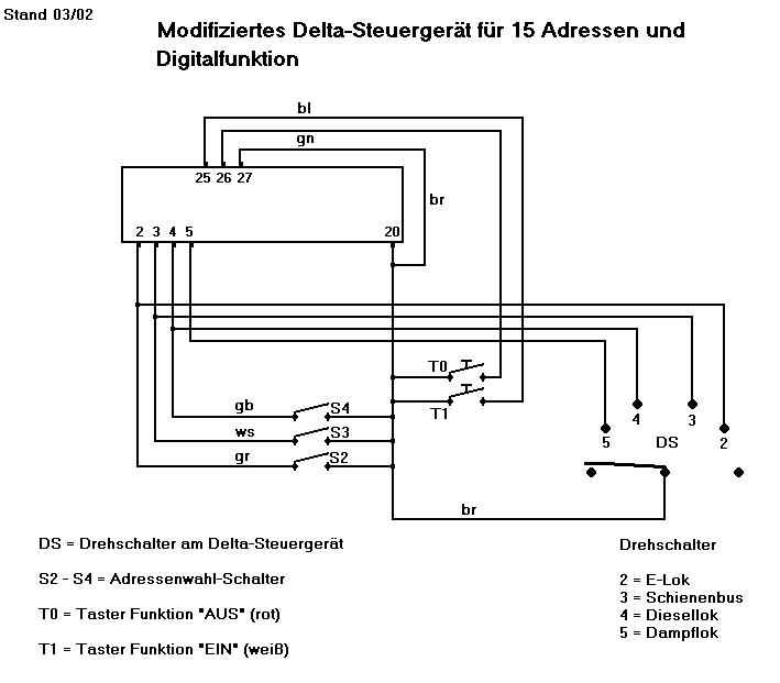
4. With 3 addional switches you can now switch Pin 4, 3, and 2 to ground and gain 10 more adresses.
These are:
6-Position-Switch on Steam (PIN 5 to ground) = Digital adress 78 (as usual)
5 and 4 switched to ground ---- adr. 08
5 and 3 / 26
5,4,3 / 56
5,2 / 62
5,4,2 / 02
5,3,2 / 20
5,4,3,2 / 54
6-Position-Switch on Diesel (PIN 4 to ground) = Digital adress 72
4,3 / NO matching Digital adress !!!!
4,2 / 06
4,3,2 /74
6-Position-Switch on Railcar (PIN 3 to ground) = Digital adress 60
3,2 / 18
6-Position-Switch on Electric (PIN2 to ground) = Digital adress 24
To control the function-output of a c80 Decoder use pushbuttons to connect PIN 26 (ON) and 25 (OFF) to ground.
NOTE: AFAIK are the adress inputs (2,3,4,5) of the 8051-Single-Chip-Computer NOT tristate. Do NOT connect them to any positive voltage !!!

Siegfried Grob wies darauf hin, daß die Verbindung der Pins 21, 22, 23, 24 und 27 mit Pin 20 bei ihm nicht erforderlich gewesen sei.

Torsten Burgdorf teilte mir mit, daß er sich an die Anleitung von Ulrich Maaß gehalten habe und das Weglassen der Verbindung Pin 27 zu Pin 20 nicht zu einem korrekten Funktionieren führe; die Verbindung der Pins 21 bis 24 zu Pin 20 sei aber nicht nötig. Er hat mir ferner einen Verdrahtungsplan seiner Änderungen überlassen:


Da ich noch keine Gelegenheit erhalten habe, diese Anleitung nachuvollziehen, kann ich sie nicht kommentieren. Probieren Sie sie (auf Ihr eigenes Risiko) aus und geben Sie Ihre Erfahrungen bekannt.

